 |
|
Phono Preamplifier |
 |
It appears that Vinyl is die hard; really there have never been in the market so many analogic turntables and cartridges, and they are not at sales prices, so it seems that Vinyl is in a very good health.
This amplifier has been designed for a high output MC, then the goal is a 42 dB gain with an input of about 3 mV at 5 cm/sec and a high acceptance; with these features it fits adequately any MM as well.
A low output MC gives a voltage 20 dB lower and this is a very demanding requirement related to noise, so probably the best solution would be an hybrid cascode with FET input.
In my mind the circuit wanted to be simple but good sounding: in every choice You have find the best trade off, and it's a matter of personal taste which is the "best" trade off.
It is not written in the Bible and there is no absolute truth: at the end of the day the gear must fit your ears.
|
Circuit and design philosophy
|
|
 |
I choose to avoid any negative feedback so I went for a passive RIAA and I believe this doesn't need further comments.
After several thinking and simulations I eventually decided a one step network, because it reduces the need for amplification stages; the trade off is a lower acceptance.
By the way a high output MC doesn't have a very high output and the maximum cutting velocity is about 15 cm/sec, so this trade off is good to me.
To get the required gain, with low noise, low distortion, not more than two stages and capability to drive difficult load (difficult for a phono preamp, of course), it wants tubes with good features, high linearity, high or very high transconductance and very low plate resistance.
|
The choice is the Russian 6C45P, an up to date version of 437WA, with a transconductance over 45 mA/V, rp about 1500 ohm (depending on steady point) and mu as high as 50 (average), used in both the gain stages.
In the input stage the high Gm with a significant plate current can resolve signals at microvolt level, and the low rp allows low resistance values in the RIAA, that is a bonus for noise.
In the output stage the low rp means a low output impedance, so the circuit can drive a 10 kohm load without loss of gain and dynamic.
The choice of fixed bias, while requiring a dedicated power supply, is worth because it avoids the cathode resistor, which would lower the transconductance if not by-passed and would require an electrolytic capacitor on the main signal path, if by-passed.
Both the stages adopt a resistor as plate load, not only for sake of circuit simplicity, but because SRPP doesn't like reactive loads (and RIAA is reactive) and works better on a well defined load value (it should be designed depending on the load): my preamp must drive at least two different loads.
Two further thoughts about RIAA network.
Would the load be fixed, as in an integrated Phono + line preamplifier where the phono stage is loaded only by the volume pot, a split RIAA could easily be used, with the 3180 µs and 318 µs nodes between the firs stage and the second, and the 75 µs node after the second stage feeding the volume pot, with the component values based on the value of the pot to get the right time constant.
This circuit would be very simple (resistive load on the second stage, no SRPP) but with the pros of split RIAA (greater acceptance, mainly).
Second thought (most important!).
The time constants of the RIAA network are three, officially, but in the reality they are more, at least four.
In recording the response over 2120 Hz rises 6dB/oct, but of course it cannot do it forever (when You have a zero You must have a pole) so, to avoid overload to cutting devices as well, a roll off at about 50 kHz has always been applied.
In reproduction the reverse (a zero at 3.18 µs) flattens the response and restores those high frequencies, present in the mater tape, which theoretically are beyond the audibility limit but in the reality build the air and naturalness of the sound.
This is the purpose of the 560 ohm resistor connected to the 4700 pF cap: it's easy to try the difference.
At the end of the nineties RIAA specs have been updated according to this topic.
|
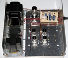
The implementation
|
|
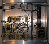 |
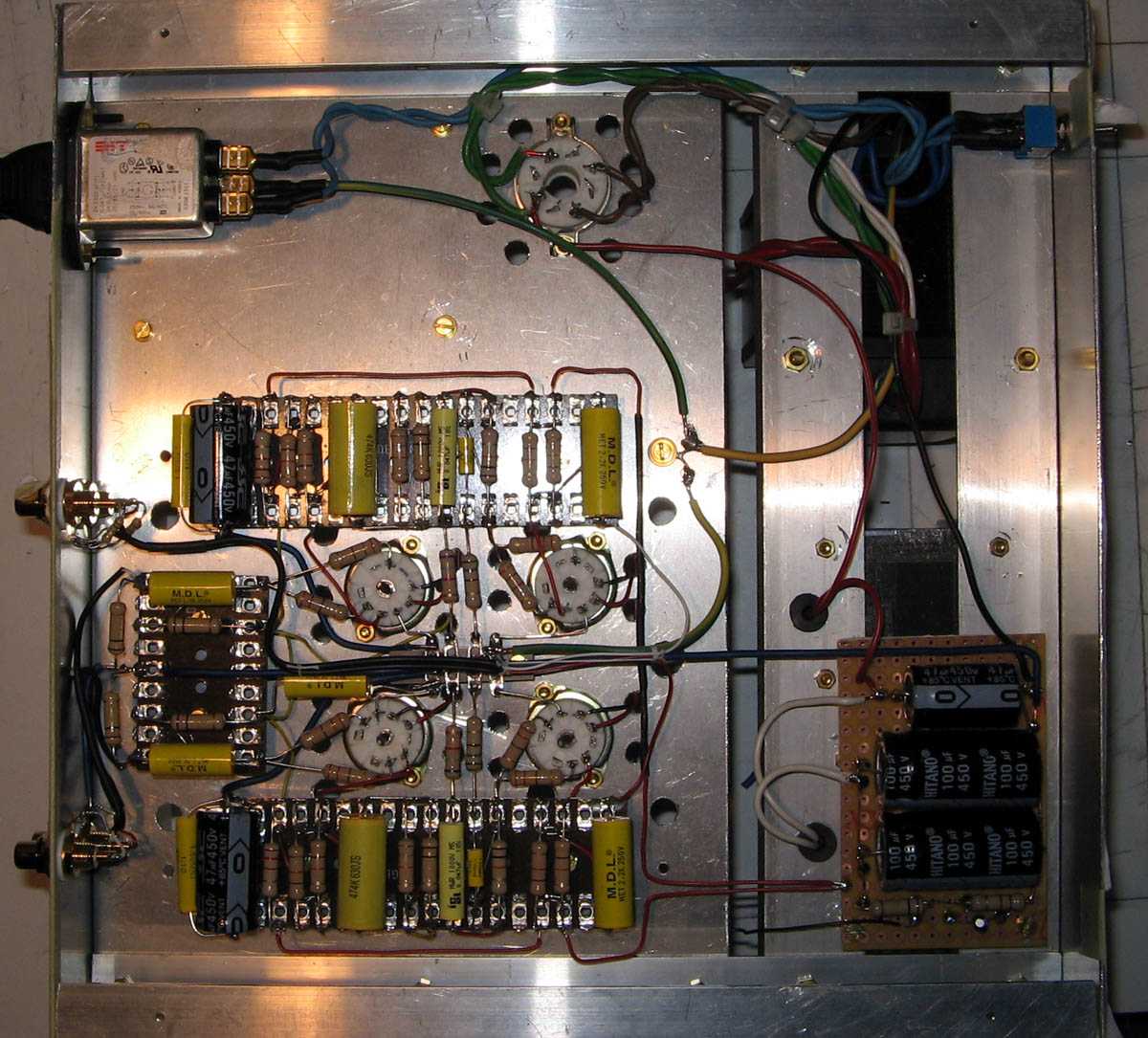
All ground connections are star wired: the star point is connected to the chassis and to the power supply with high section wires.
The circuit is wired point to point, all components are soldered to wiring strips or to the pins of the sockets, no flying junctions.
Grid bias is through 100 kohm resistors: 6C45P requires at maximum 150 kohm with fixed bias; in the second stage bias is connected at top of RIAA network, in order not to load it.
|
The common of the bias for al the tubes is star grounded with a 1 µF cap (besides the 10 µF on the supply card).
The 100 kohm resistor on the input, being paralleled with the bias resistor, gives an input impedance of 50 kohm: that resistor is intended to be tweaked to obtain the input impedance required by the cartridge (this also is a matter of taste: it depends on the brilliance You want).
|
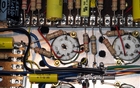 |
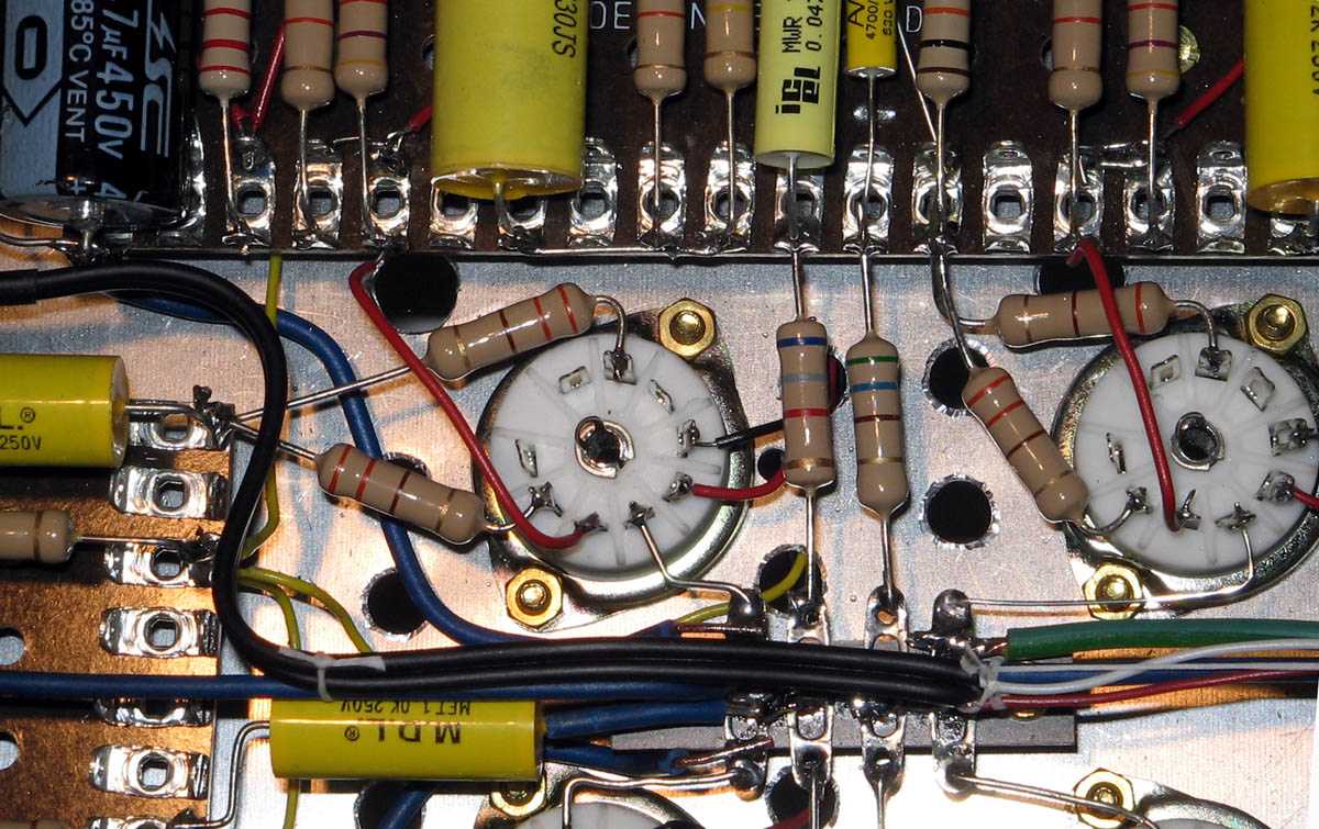
In the schematic and in the physical circuit as well You see two grid stopper resistors per each tube: 6C45P has the grid connected to two pins of the socket and very easily oscillates at high frequency (several MHz).
Both the grid pins must be connected to stopper resistors, which must be soldered very close to the pin itself, as can be seen in the photo.
|
The plate loads are made with two resistors 47 kohm, 2 W, paralleled.
All resistors are 2 W, carbon: they sound better.
|
The Power Supply
|
|
 |
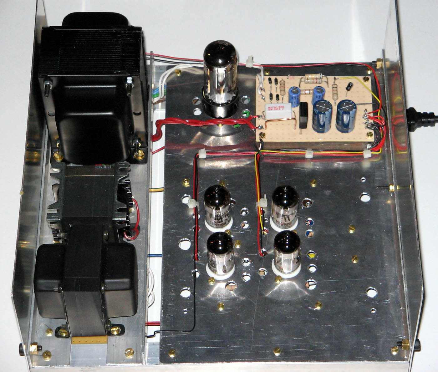
The filament and bias supplies are mounted on a card on the upper side of the chassis.
The filaments supply is DC non regulated, elevated some 10 V over the cathode: it works well.
High voltage supply is based on the classical 5Y3, in my opinion a very good choice, regarding switching noise.
The filter is two stage LC, chocke input, again the best choice for a good filtering, even if not cheap.
The first chocke is a Sowter specific for choke input, this kind of filter requires a very high insulation.
I do not like series regulators because they use high negative feedback, which is bad sounding.
In the physical circuit there is a filter at the AC input, not present in the schematic.
|
Adjustment
|
|
There is no need for tweaking, but the tubes require a long burning: at least 3 hours to stabilize the steady current (at the beginning the current oscillates more than 10%) and many more to smooth every "hardness": at the end the sound is silky and detailed but very fast, dynamic and "muscular" at need. |
|
|
|