 |
|
Fermat:
Push Pull line Amplifier
|
|
(click the images to enlarge)
Forewords
This amplifier is the implementation of a topology developed in the
beginning of 19th century by the engineers of Western Electric,
realized with the most recent components.
During the first years of 1900 Lee de Forest invented the vacuum tube
and the engineers of Western Electric developed the new device: in
those years telephone network was rising and needed new tools to
implement long distance communication.
The term “line” in those years meant several miles
of twin
cable, definitely a hard load, and the amplifier had to be made with
the phisical devices available at that time, so the topology had to be
a “smart” one.
Today a line amplifier has a different purpose: it is aimed to select
from several inputs and drive a power amplifier (or a mixing console or
some other device, like a DAC) throug few feets of shielded cable.
So, why a Push Pull in a low power amplifier?
Design philosophy
Why
a complex and expensive technology at the beginning of the 2000, in
this age of monotriodes with RC loading, in the pure philosophy
“less is better”?
Well, it's a matter of what you require from a “line
amplifier”: I agree that simple is better, but Albert
Einstein
said “do it as simple as possible, but not more”.
I think that today someone is selling simplicity for effectiveness.
Monotriode is simple, so it “must” sound better,
but if you
try and you have some requirement, not very particular at the end of
the day, you realize that it is too much simple to work properly in any
non trivial case.
Well, if you like the sound of the monotriode because it is
“warm” and “euphonic” (this
terrific word is
over-used from the 80', the years of the
“audiophiles” aka
“golden ears”, those people that think that
connecting a
wave generator and a scope to an amplifier pollute it without remedy)
this project is not your cup of tea and I will not waste your time to
convince you that you are listening only to paramount of second
harmonic distortion.
And I'm not speaking about negative feedback.
OK, if you need only a couple of volts RMS or less, on a load of a
megaohm or so, a monotriode can work.
So, why a push pull and transformer amplifier?
This
amplifier has to drive different loads, a 600 ohm balanced line, a
standard (0 dBu 47 kohm) unbalanced and a low level low impedance (my
DAC) unbalanced line.
It has to select several inputs, standard HiFi sources and a 600 ohm
balanced line.
It must have the lowest distortion, because it is not the last stage of
the chain, and it is driving different devices, so it is not possible
to think of harmonic elimination; any distortion produced by the stage
will be furtherly amplified and distorted by the following, in a
totally unpredictable way.
Deep Class A push pull because it gives the lowest distortion without
negative feedback: even order harmonic distortion is naturally
cancelled in a push pull configuration, odd order harmonics depends
only on the tube you are using.
Transformer interface (both input and output) is justified by the
presence of balanced lines both on input and on output.
The function of balanced line is to reduce the common mode noise, i.e.
the noise (hum, buzz) captured by the cable or generated by stray
currents flowing trough the shield of the cable.
 The
most effective way to get a high CMRR is the use of a transformer: find
a technical explanation here (Jensen Transformer application
Note). The
most effective way to get a high CMRR is the use of a transformer: find
a technical explanation here (Jensen Transformer application
Note).
Transformer
input stage is an answer to these requirements: 1. high CMRR, which is
not very important in common HiFi systems, where connection cables are
very short but is a must connecting a mike amp, where the mike
amplifier is near the mikes and not near the line amp, 2. avoiding
potentiometers: standard quality pots are a source of noise and
scratch, with age, while premium quality pots or switches with set of
selected resistors do not cost too much less than a transformer and in
my opinion sound worse.
This topology is worth if you choose a good tube, that's why I chosed
the twin triode ECC99.
 This
is a strong tube, which can feed high current (don't forget 600 ohm
load and deep class A bias), very very linear (it has a negligible
third harmonic distortion, while 6DJ8, e.g., has not) and it's gain
fits perfectly the requirements of a line amplifier. This
is a strong tube, which can feed high current (don't forget 600 ohm
load and deep class A bias), very very linear (it has a negligible
third harmonic distortion, while 6DJ8, e.g., has not) and it's gain
fits perfectly the requirements of a line amplifier.
Would I need a lower gain the choice would be 6H30.
These tubes come from recent production, they are not phase out, 6H30
is for military use.
NOS tubes are not justified, neither by cost reason (ECC99 and 6H30 are
not cheap, but nothing to compare with current prices of some NOS
tubes) nor by availability: I'm not sure that next year I will find a
new one, would I need.
Any device must be maintainable, at reasonable cost.
And who can swear on a small glass tube which has been stored (if we
are lucky, otherwise transported with which care?) for 20 or 30 years?
|
The schematic
The schematic is on the right.
It's very simple, from a conceptual point of view.
Let's examine the stages.
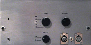
Input
stage
Input stage is formed by an input selector and a transformer which
functions as volume control also.
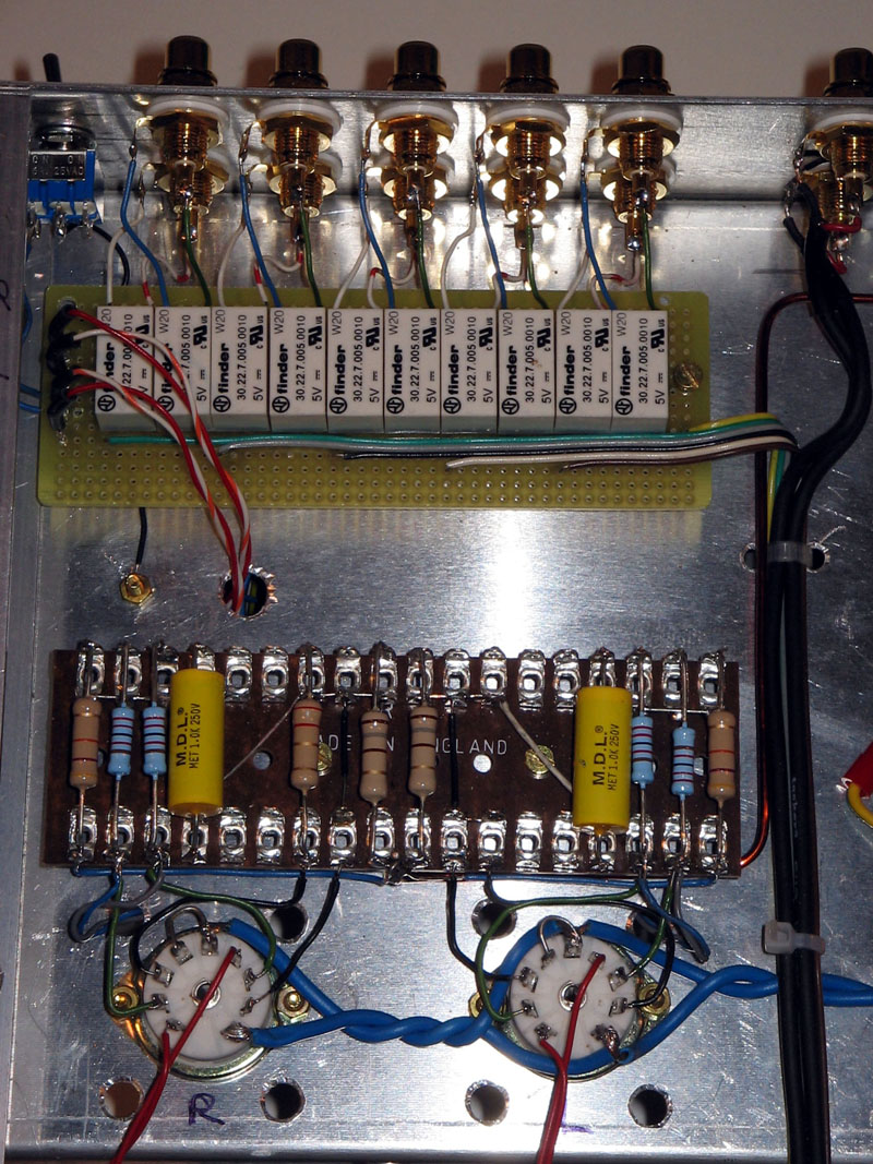 Input selector is
realized by means of relais switches: as you can see on the shematic
both hot and ground poles are switched. Input selector is
realized by means of relais switches: as you can see on the shematic
both hot and ground poles are switched.
So at any moment only one source is electically connected to the
amplifier, reducing ground loops and allowing the use of balanced lines.
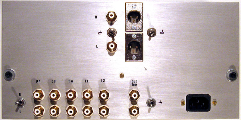
In this implementation I have one only XLR connector (per channel),
mounted on the front panel and paralleled to a chinch
connecor
(but they cannot be used together).
A “ground lift” switch can connect to ground one
pole of the input winding, in some cases lifting it can reduce hum.
The XLR connector has its own “ground lift” switch
connecting to ground the shield of the balanced cable: in this case the
ground lift of the primary of the transformer must be off.
Input transformer is the Sowter 9335: its secondary has 27 positions,
stepped 2 dB, and 1:1 ratio on the 0 dB
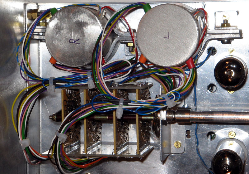 step. step.
I used a 24 steps switch because it's almost impossible to
find a 27 steps switch; the gain is more than enough so I dropped the
0dB, the -4dB and the -50 dB positions of the secondary winding, but
any other selection of course is OK.
Amplifying
stage
It is a push pull ECC99 based, with the cathode resistor not bypassed.
The null point of the input is realized by the junction of the two
resistors connecting the grids: the series of the resistors give the
correct load to the transformer.
The junction is connected via a capacitor to the connection of the
cathodes (this is the signal ground) and to the electric earth with a
47 kohm resistor for biasing (supply ground).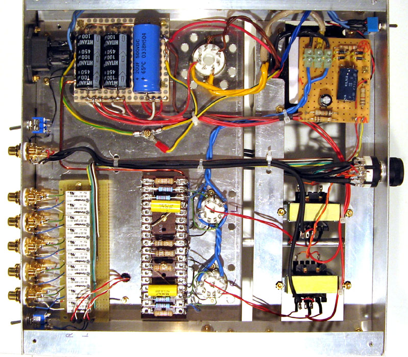
This capacitor cancels any stray signal due to any tolerance in
components.
A small resistor can be connected to one of the cathodes (not
necessarily) just to compensate for small tolerances between the
triodes parameters.
This resistor is not present in the schematic because it is not always
necessary: in my case a 2.2 ohm resistor is connected to a single
triode cathode of one ECC99, the other didn't need any compensation; it
is clear tha the construction tolerances between the two triodes in a
tube are very small.
The schematic is very simple, I didn't use grid stopper resistors
because of the low global gain and I didn't detect any oscollation at
the scope.
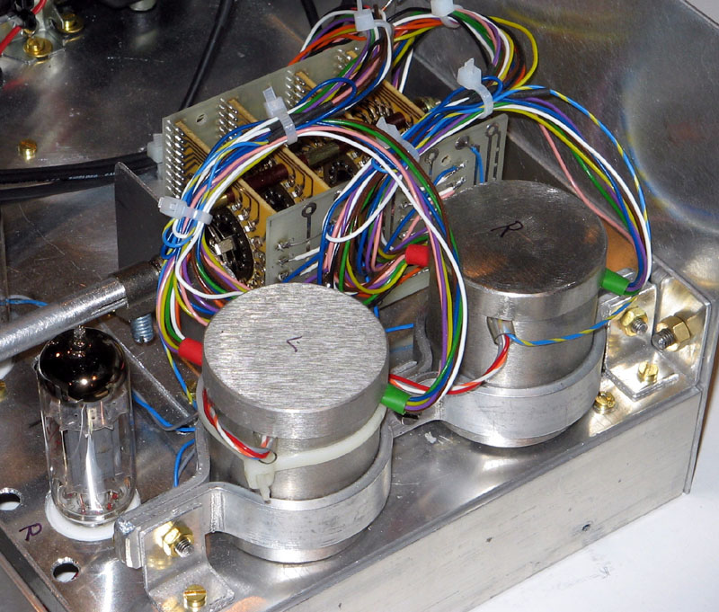
Output
stage
It consists of the output transformer, Sowter 9041, and the output
selector.
The output transformer offers excellent features (120 kHz bandwidth
with negligible distortion) but these features require a current
unbalance better than (i.e. less than) 0.5 mA: so the anode currents in
the PP must be perfectly balanced; tweaking procedure is described in
the last paragraph.
Instead of 9041, the Sowter 9900 can stand an unbalance up to 5 mA,
with much higher cost and size.
Winding ratio is 5:1 (total primary on total secondary), for a load of
600 ohm with max output level 11 V RMS and distortion less than 0.5%.
Output selector drives a XLR and a chinch (RCA) connector, each with
ground lift switch.
That allows to use two different types of output without disconnecting
the cables.
The output transformer features another secondary winding, with 10:1
ratio, not mentioned in the schematic.
It can be used for negative feedback or not connected; I used it to
have one more low level / low impedance output.
Power
supply
This is my classic tube supply with choke input.
It's not worth spending words about the pro's of this type of supply,
which are well known.
The only con is that it needs a high voltage choke in the first stage,
I used a Sowter 8970.
The rectifier is 5Y3, which features an excellent noise figure (perhaps
the best) for low voltage and low current.
It is a direct heating tube, so it must be in vertical position.
Filaments are AC powered, I do not think that in a line amplifier DC
heating is necessary; lifting heaters about 20 V is enough and this
also improves the life of the tubes.
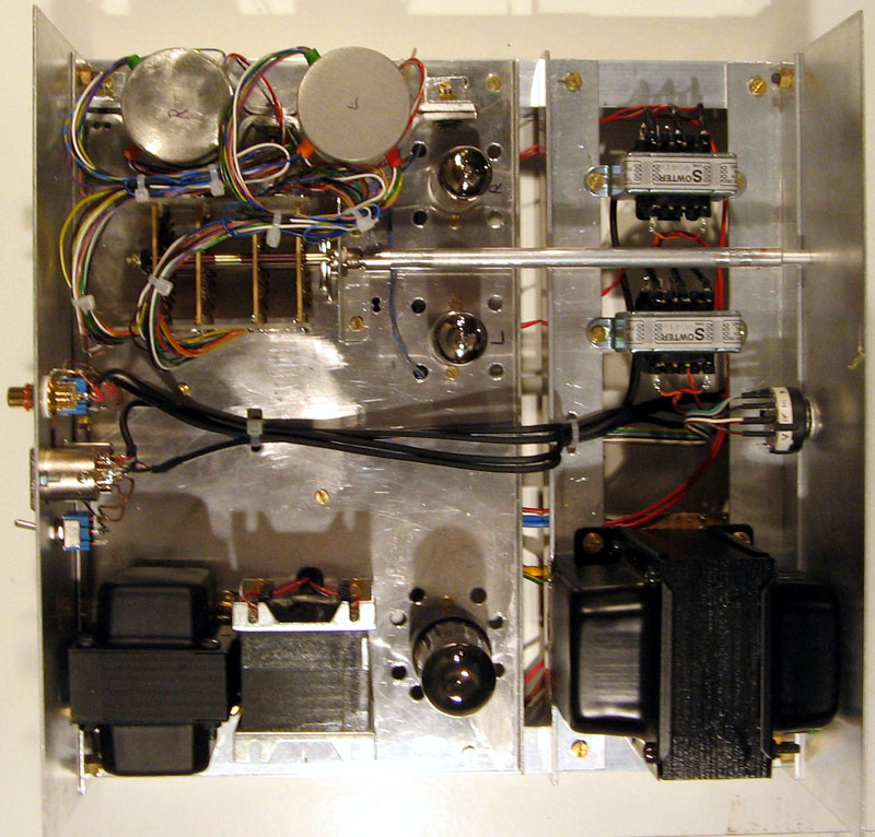
Building
it
It's built on an aluminium chassis and point to point wiring.
The input transformers do not have threaded holes, so an aluminium
clamp fixes them to the chassis.
Ground is star-wired and connected to the chassis, together with earth
from the AC outlet (this is mandatory for safety because the chassis is
aluminium).
All transformers are mounted with brass screws using a non-magnetic
screwdriver.
Tweaking
There is only one tweaking to do:
balancing anodic current in each push-pull.
This is simple from a conceptual point of view, but it requires a
little work and patience.
As I told before, current in the windings of the OT must be balanced,
in order not to magnetize the core and worsen its performance.
This balance must be effective from the very first power on, because
few minutes of unbalanced currents can magnetize the core.
So currents must be balanced before hooking up the transformers and
after burning the tubes: during the first hours anodic current can vary
over 10% and, with a stady state at 14 mA this is enougf to damage the
transformer (this damage is not permanent, a dedicated de-magnetizing
procedure is in place, but it is more complex than the tweaking
procedure I'm describing).
 More: the tweaking
must be done with the chassis upside-down, but 5Y3 must work in upright
position. More: the tweaking
must be done with the chassis upside-down, but 5Y3 must work in upright
position.
So the tweaking is performed without 5Y3, with a solid state rectifier
simulating the tube.
The rectifier is built with 1N4007 diodes, each one in series with a
wirewound resistor 330 ohm, 5 W.
Diodes and resistors are mounted on an insulated board and connected to
the circuit with “flying” cables (be sure about
insulation,
there are hundreds volts on an open board).
First operation:
connect the temporary rectifier instead of 5Y3, do not connect the
transformers, connect the four anodes to the power supply, the cathodes
to the cathode resistors (the 180 ohm ones) and go on burning the tubes.
To stay on the right side check the total current (about 55 –
65 mA) and voltages.
Burn the tubes for at least 48 hours, better with some interruptions;
during the first hours you will see current varying, then stabilized.
Now we can balance the currents, one tube at a time.
I did not use trimmer because I do not think they work properly with
high current (15 mA is high current for a standard trimmer) and btw I
couldn't find 10 ohm trimmers.
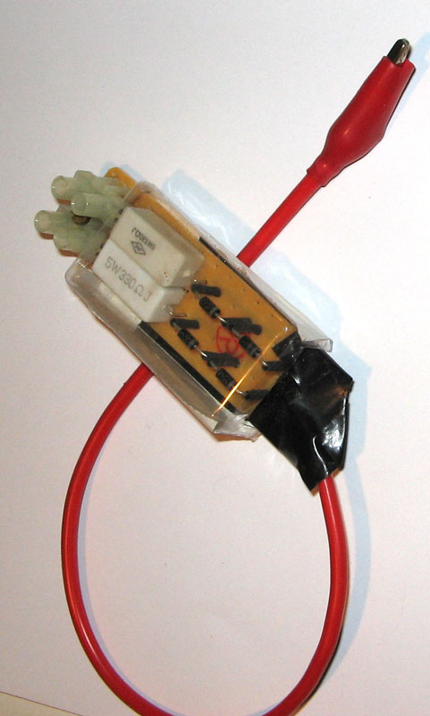
Second operation:
mount on a small board the device of Fig. 9, where we have two
identical branches built with low value resistors (1, 2.2, 4.7 ohm) in
series and each one shorted by a copper wire bridge; the branches are
connected to the cathode resistor (180 ohm) together at one side and to
the catodes of the tube at the other side.
Then connect a mA-meter in series with each anode (so you need two
identical mA-meters): DANGER the instruments are connected to high
voltage, so they must be put on an insulated board and the cables must
be in perfect conditions.
Third operation:
switch on the power and check anodic currents: if they differ, insert a
resistor on the cathode of the triode which is conducting more current,
simply cutting one of the short-circuit wires in parallel with the
resistors (Fig. 9): sure in not more than two trials you find the right
value, so remove the device, connect a resistor with the value found to
the cathode of the tube, a wire to the cathode of the other tube.
Repeat for the second tube from second operation (solder again the
short-circuit wire(s)).
As I told, in my circuit one of the ECC99 didn't require any resistor,
the other only 2.2 ohm.
Double check the current balance, then remove the mA-meters and connect
the transformers, remove the temporary rectifier, put the chassis in
upright position and put the 5Y3 on its place.
That's it.
|
|
|
